JetsonNano摄像头驱动开发指南
JetsonNano摄像头驱动开发指南
参考手册:NVIDIA Jetson Linux Developer Guide(下文中所指的参考手册均是指该手册)
Jetson资料下载中心:Jetson Download Center | NVIDIA Developer
Jetson Nano 信息:
- Linux jetson-desktop 4.9.253-tegra
- L4T 32.7.1
platform代码:
- t234:Jetson AGX Orin
- t194:Jetson Xavier NX 系列、Jetson AGX Xavier 系列
- t210:jetson nano、jetson tx1
内核定制化
下载编译内核
从Jetson Linux | NVIDIA Developer处下载最新的(或者自己选L4T版本号)内核源码L4T Driver Package (BSP) Sources
注意:
- 目前(2022/6/4)L4T 34.1之后,暂时只支持 Jetson AGX 系列和 Jetson Xavier 系列,其余暂不支持
- 下载的是源码包(L4T Driver Package (BSP) Sources)
- 也可以通过SDK Manager来直接下载,eg:
./source_sync.sh -t tegra-l4t-r32.7.1
解压TBZ2文件:
1 | tar -xjf public_sources.tbz2 |
安装工具链:
注意:
- 如果在jetson nano上则不需要该步骤
- 官方推荐
Linaro gcc 7.3.1 2018.05 aarch64参考连接:本文最开始说明的参考手册中
Kernel Customization -> Jetson Linux Toolchain
解压:
1 | mkdir $HOME/l4t-gcc |
编译内核:
1 | # 安装依赖 |
编译生成的内核以及设备树在:
- 内核:
TEGRA_KERNEL_OUT/arch/arm64/boot/Image - 设备树:
TEGRA_KERNEL_OUT/arch/arm64/boot/dts/
编译内核模块
找到内核的头文件目录:
-
对于在jetson上编译来说,头文件在
/usr/src/linux-headers-$(uname -r)-ubuntu18.04_aarch64或/lib/modules/$(uname -r)/build -
对于其他平台来说,需要下载内核源码并解压,按照上述操作,之后运行以下命令:
1
make ARCH=arm64 O=$TEGRA_KERNEL_OUT -j<n> modules_prepare
编译:
1 | cd <path_to_module_source> |
摄像头驱动开发
官方提供两种开发方式:
- Camera Core Library接口
- 直接通过V4L2访问
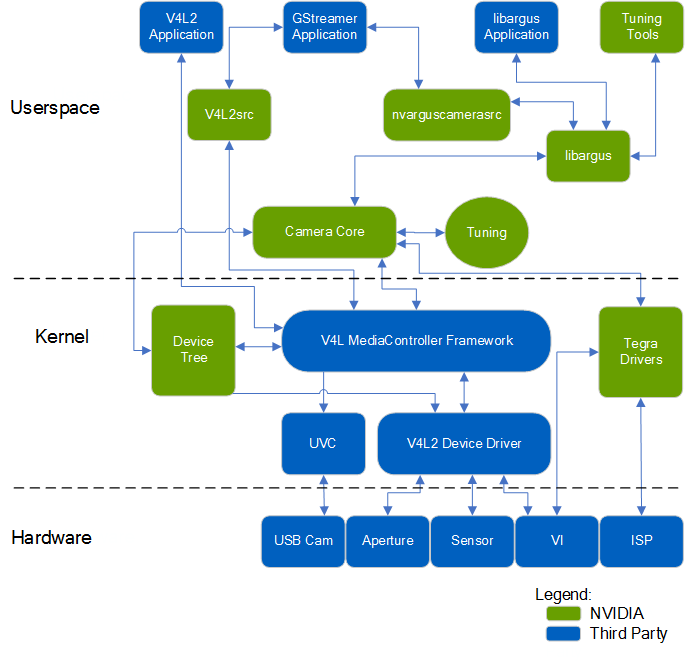
对于Camera Core Library来说,Linux Driver Package (L4T)框架上的引用和内核模式的V4L2驱动之间的关系如下所示:
对于直接通过V4L2访问和方式来说,其驱动于应用之间的关系为:
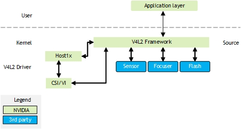
对于这种方式,需要:
- 在内核中添加设备树节点
- 开发对应的V4L2驱动,对于该驱动官方有两种版本,建议用最新的2.0。以下为可以参考的Sony IMX185驱动代码
- Version 1.0 driver: imx185_v1.c
- Version 2.0 driver: imx185.c
设备树
位置
参考手册中:Bootloader -> U-Boot Customization -> Environment Configuration -> exlinux.conf
在L4T中,一般最后的设备树启动文件*.dtb在根文件系统的/boot/dtb/下,同时可以通过以下命令找到具体位置:
1 | cat /sys/firmware/devicetree/base/nvidia,dtsfilename |
- 默认位置:
- Jetson Nano:
XXXX/hardware/nvidia/platform/t210/porg/kernel-dts/tegra210-p3448-0000-p3449-0000-b00.dts - Jetson Xavier NX:
XXXX/hardware/nvidia/platform/t19x/jakku/kernel-dts/tegra194-p3668-all-p3509-0000.dts
- Jetson Nano:
同时通过/boot/extlinux/extlinux.conf配置文件(参见EXTLINUX - Syslinux Wiki)可以使得uboot通过dtb overlays的方式选取不同的设备树或者启动参数来启动系统,对Linux驱动编写与调试方便很多
如下所示为本文中对应的脚本:
1 | TIMEOUT 30 |
其中:
- TIMEOUT:默认等待选择时间
- DEFAULT:默认启动方式
- LINUX:Linux内核存放位置
- FDT:设备树文件(不指定则用默认位置,即/boot/dtb/下文件)
- FDTOVERLAYS:xxx.dtbo文件,用于补充或者覆盖设备树文件中的一些配置(uboot会根据该文件自动修改设备树)
通过上述命令编译设备树后,其生成的*.dtb文件会出现在output/arch/arm64/boot/dts下,
调试
设备树目录:/proc/device-tree(软连接)和/sys/firmware/devicetree/base/(实际位置)
1 | # 调试 |
基础含义
在设备树文件<top>/hardware/nvidia/platform/t19x/common/kernel-dts/t19x-common-modules/tegra194-camera-imx185-a00.dtsi中找到tegra-camera-platform节点
在tegra-camera-platform节点中创建一个模块表(module table),每个模块必须包含其基本信息和该节点内设备的定义
如下所示为一种典型的节点:
1 | tegra-camera-platform { |
属性含义:
- badge:标识此模块的唯一名称。
- 名称必须由三部分组成,用下划线隔开:
- 模组的摄像头板卡ID (camera_board_id)
- 模块的位置,例如后置(rear)或前置(front)
- 模块的零件号,可在模块数据表中找到。如果零件号不可用,请使用唯一标识符。只有零件号的最后六个字符是有效的
- 例如,imx185_rear_liimx185代表一个模块,该模块带有一个后置imx185摄像头,零件号为“llimx185”
- 如果系统有多个相同的模块,则每个模块必须具有不同的位置,从而使模块名称唯一
- 名称必须由三部分组成,用下划线隔开:
- position:相机位置。支持的值取决于系统中的摄像机数量
- 在双摄像头系统中:rear 和 front
- 在三摄像头系统中:bottom、top 和 center
- 在六摄像头系统中:bottomleft、bottomright、centerleft、centerright、topleft 和 topright
- orientation:传感器方向;表示传感器方向的数字索引。索引和方向之间的关系是任意的,但通常在双摄像头系统中,0 是“后向”,1 是“前向”
单独成像设备
成像设备是相机模块内部的组件。有可能:
- 一个传感器
- 一个聚焦器
- 一个闪光灯
必须将信息添加到设备树节点以支持设备操作。对于每个设备的设备树节点,分配一个包含以下内容的设备树节点:
- 设备名称
- 器件的从地址(可从器件数据表中获得)
- 标识节点的兼容属性
注意:除了引用其他设备树节点的设备外,与相机相关的设备树节点中的所有值字段都必须使用字符串数据类型。
以下是IMX185 V4L2传感器驱动程序的设备树节点示例:
1 | imx185_a@1a { |
设备属性
下表介绍了V4L2传感器设备的设备树节点属性(其中*号为可选项)
以下属性可以在不同的 DTSI 文件中指定。例如,时钟、GPIO 和调节器属性可以在platform DTSI 文件中指定,其余属性可以在sensor DTSI 文件中指定
| 属性 | 值 |
|---|---|
| compatible | 设备标识符。 Linux 内核使用此关键字将设备驱动程序绑定到特定设备 |
| reg | I2C 从机地址 |
| mclk* | 设备输入时钟的名称。默认值为 extperiph1。 extperiph1 的最大频率为 24 MHz。如果需要大于 24 MHz 的频率,请使用外部时钟源。 如果传感器使用相机模块提供的时钟源,则不需要 |
| 设备的通用输入/输出 (GPIO) 引脚,其中 相机的默认 GPIO 引脚为: • H3-gpio:Camera0 复位 • H6-gpio:Camera0 断电 • T6-gpio:Camera1 复位 • T5-gpio:Camera1 断电 如果传感器有自己的 I/O 控制机制并且不需要来自 Jetson 的特定 I/O 控制,则不需要 |
|
| 指定设备的监管者(regulator),其中 定义的监管者存在以下: • vana-supply:值必须是<&en_vdd_cam_hv_2v8>(模拟2.8v)。 • vdig-supply:值必须是<&en-vdd-cam_1v2>(数字1.2v)。 • vif-supply:值必须是<&en-vdd-cam>(接口1.8v)。 • vvcm-supply:值必须是<&en_vdd_vcm_2v8>(vcm 模拟2.8v)。 如果传感器使用相机模块提供的电源,则不需要 |
|
| 监管者(regulator)的唯一标识符,其中 定义的监管者为: • avdd-reg:vana • dvdd-reg:vdig • iovdd-reg: vif • vcmvdd-reg:vvcm |
|
| physical_w | 传感器的物理宽度(毫米) |
| physical_h | 传感器的物理高度(毫米) |
| sensor_model* | 此模块中的传感器类型,例如“imx185” |
| set_mode_delay_ms* | 捕获开始后第一帧的最大等待时间(毫秒) |
| post_crop_frame_drop* | 传感器裁剪设置后,驱动程序要丢弃的帧数 一些传感器必须丢帧以避免在应用裁剪设置后接收到损坏的帧 |
| use_decibel_gain* | 布尔值,默认值为 false。根据以下公式确定驱动器是否返回以分贝 (dB) 为单位的模拟增益: dB = 20 * log(Analog Gain) 如果为 false,则返回驱动器接收到的模拟增益,不作任何更改 |
| delayed_gain* | 布尔值,默认值为 false。如果为真,则用户模式驱动程序将延迟一帧发送更新的增益值。如果为 false,它会立即将更新的增益值发送给驱动程序。 |
| use_sensor_mode_id* | 一个布尔值,默认值为false。如果为true,用户模式驱动程序将绕过默认模式选择逻辑,并使用TEGRA_CAMERA_CID_SENSOR_MODE_ID 控件选择特定的传感器模式。如果为false,则使用默认模式选择逻辑,该逻辑根据分辨率、颜色格式和帧速率选择模式。 |
属性值对
此表描述了适用于 V4L2 实现的传感器模式的属性值对。所有属性都是按模式设置的,并且必须精确设置。
| 属性 | 值 | |
|---|---|---|
| mode |
指定这组属性适用的传感器模式,其中 |
|
| ports | 媒体控制器图形绑定信息。有关更多信息,请参阅端口绑定 | |
| mclk_khz | 标准MIPI驱动时钟频率,单位为kHZ | |
| num_lanes | 传感器输出的通道数 | |
| tegra_sinterface | 选择NVIDIA® Tegra®的那个串口,如"serial_a" | |
| discontinuous_clk | 布尔值;指示传感器是否在MIPI通道上使用不连续时钟 | |
| cil_settletime | MIPI 通道的 THS 稳定时间,以纳秒为单位。使用适当的公式计算可接受值的范围。 •对于 NVIDIA® Jetson™ Nano 设备和 Jetson TX1:  其中一个 lp 时钟周期为 1/(102 MHz)。 其中一个 lp 时钟周期为 1/(102 MHz)。•对于 NVIDIA® Jetson AGX Xavier™ 系列和 Jetson TX2 系列:  其中一个 lp 时钟周期为 1/(204 MHz)。 其中一个 lp 时钟周期为 1/(204 MHz)。UI 是单位间隔,等于时钟通道上 HS 状态的持续时间。 如果该值为 0,则驱动程序会尝试根据 mclk_multiplier 参数进行自动校准。 有关详细信息,请参阅 D-PHY 的 MIPI 联盟规范。 |
|
| dpcm_enable | 布尔值;指定是否为此模式启用DPCM压缩 | |
| active_h | 指定像素活动区域的高度 | |
| active_w | 指定像素活动区域的宽度 | |
| pixel_t | 已弃用。请改用以下属性: •mode_type •csi_pixel_bit_depth •pixel_phase |
|
| mode_type | 传感器模式类型。可能的值为: •yuv •bayer •bayer_wdr_pwl:宽动态范围模式。使用分段线性函数来压缩多重曝光融合的像素数据。传感器上也进行了多次曝光融合。 有关详细信息,请参阅 IMX185 传感器驱动程序文档 |
|
| readout_orientation | Specifies clockwise rotation in degrees of the sensor image presented on the display. Intended for use in an Android environment; has no effect with Jetson Linux Driver Package.This property is used to ensure that the sensor image display is oriented correctly for the end user.For example, suppose the sensor is rotated 90° counterclockwise, so that the top of the image falls on the right side of the sensor’s imaging surface. The image on the display appears to be rotated 90° clockwise, with the top of the sensor’s imaging area at the top of the display, and the top of the image on the right. To correct this, set readout_orientation=270. This rotates the displayed image 270° clockwise (90° counterclockwise), rotating the top of the image from the right side of the display to the top. | |
| csi_pixel_bit_depth | Bit depth of sensor output on the CSI bus.If mode_type is set to bayer_wdr_pwl, this property represents the bit depth of sensor output after piece-wise linear function based compression.For more information, see the IMX185 Sensor Driver documentation. | |
| dynamic_pixel_bit_depth* | True dynamic range of the signal.If mode type is set to bayer_wdr_pwl, specifies the bit depth of the multi-exposure fused output before piece-wise linear function based compression.For other mode types, must be equal to csi_pixel_bit_depth.For more information, see the IMX185 Sensor Driver documentation. | |
| pixel_phase* | Sensor pixel phase. Possible values are: | |
| •uyvy•vyuy•yuyv | •yvyu•rggb•bggr | •grbg•gbrg |
| For more information, consult to the IMX185 Sensor Driver documentation. | ||
| line_length | Pixel line width horizontal timing size for the sensor mode. Used to calibrate the features in the camera stack.The value must be greater than or equal to active_w. | |
| mclk_multiplier(deprecated) | MCLK multiplier for timing the capture sequence of the hardware. Calculate this value with the equation:mclk_multiplier = desired ISP clock frequency in Hertz / mclkThe value must be greater than pixel_clk_hz divided by mclk to prevent ISP underrun.This switch is no longer needed because the value it specifies is calculated internally. | |
| pix_clk_hz | Sensor pixel clock for calculating exposure, frame rate, etc.Calculate the value based on the input clock (mclk) and PLL settings from sensor mode table. See the sensor data sheet for detailed instructions.For more information, see [Sensor Pixel Clock](https://docs.nvidia.com/jetson/l4t/Tegra Linux Driver Package Development Guide/camera_sensor_prog.48.2.html#wwpID0EBHA). | |
| serdes_pix_clk_hz | Output clock rate for the serializer/deserializer (GMSL or FPD link), in Hertz. Required only for camera modules that use SerDes.For more information, see [SerDes Pixel Clock](https://docs.nvidia.com/jetson/l4t/Tegra Linux Driver Package Development Guide/camera_sensor_prog.48.2.html#wwpID0EBHA). | |
| inherent_gain | Gain obtained inherently from the mode, that is, pixel binning.May be set to 1 if you do not know the actual value. | |
| min_gain_val | Minimum gain limit for the mode. The value is rounded down to six decimal places. Usually set to 1.0, representing 1x gain. | |
| max_gain_val | Maximum gain limit for the mode. The value is truncated to six decimal places.If supported by the sensor, it may be increased to include digital gain. | |
| min_exp_time | Specifies the minimum exposure time limit for the mode, in microseconds. The value is rounded up to an integer.Calculate the value according to this equation:min_exp_time = (minimum coarse integration time) * line_ length / pix_clk_hz * 1000000The minimum coarse integration time is the minimum exposure intervals. Unit in lines. | |
| max_exp_time | Specifies the maximum exposure time limit for the mode, in microseconds. The value is rounded up to an integer.Calculate this value with the equation:max_exp_time = (maximum coarse integration time) * line_length / pix_clk_hz * 1000000The maximum coarse integration time is the maximum exposure intervals. Unit in lines. | |
| min_hdr_ratio | Minimum high-dynamic-range (HDR) ratio denominator for the mode for HDR sensors. Must be an integer greater than 0. For non-HDR sensors, set to 1. | |
| max_hdr_ratio | Maximum HDR ratio denominator for the mode for HDR sensors.Must be an integer greater than 0. For non-HDR sensors, set to 1. | |
| min_framerate | Minimum frame rate limit for the mode, in frames/second (fps). The value is rounded down to six decimal places.Calculate this value with the equation:min_framerate = pix_clk_hz / (line_length * maximum frame length) | |
| max_framerate | Maximum frame rate limit for the mode in fps. The value is rounded down to six decimal places.Calculate this value with the equation:max_framerate = pix_clk_hz / (line_length * minimum frame length) | |
| embedded_metadata_height | Specifies the number of extra embedded metadata rows for each frame.Set to 0 to disable embedded metadata support. | |
| num_control_point* | Number of control points used in the piece-wise linear function for compressing multi-exposure fused pixel data. Multi-exposure fusion is also performed on the sensor.Valid if mode_type is set to bayer_wdr_pwl.The camera core library interface supports up to 9 control points.For more information, see the IMX185 Sensor Driver documentation. | |
| control_point_x_[ |
X coordinate of control point |
|
| control_point_y_ [ |
Y coordinate of control point |
|
| For WDR DOL (Digital Overlap) sensors | ||
| num_of_exposure† | Number of exposure frames in a DOL multi-frame. | |
| num_of_ignored_lines† | Number lines to crop at the top of each exposure frame. Usually includes the OB (Optical Black) rows and ignored area of effective pixel rows, both of which use the same LI (line information) header as the exposure frame on which they reside. The VI (video input) module handles cropping for these lines. | |
| num_of_lines_offset_0† | Number of VBP rows appearing in a single exposure frame of a two-exposure DOL multi-frame. These VBP rows are filtered out as they have LI (line information) indicating that they are blank.Note that the same number of VBP rows appear at the end of a long exposure frame and at the start of a short exposure frame.For DOL mode with two exposure frames, there is only one type of VBP row. With more than two exposure frames, there may be different types of VBP rows. Hence the parameter can be extended to number_of_offset_1, number_of_offset_2,…. The number of VBP row types is usually one less than the number of exposure frames in a DOL frame. | |
| num_of_ignored_pixels† | Size of LI (line information) header for each row, in pixels. The line information helps differentiate VBP (Vertical Blank Period) rows and different exposure rows such as long exposure and short exposure. The VI (video input) module handles cropping for these lines. | |
| num_of_left_margin_pixels† | Size of the left margin, before the active pixel area, in pixels. These lines are required for cropping alignment. The VI (video input) module handles cropping for them. | |
| num_of_right_margin_pixels† | Size of the right margin, after the active pixel area, in pixels. These lines are required for cropping alignment. The VI (video input) module handles cropping for them. |
测试
参考手册中:
- Multimedia -> Accelerated GStreamer -> Camera Capture with GStreamer-1.0
- Camera Development -> Sensor Software Driver Programming -> Device Registration
1 | # 安装依赖 |